
The entire article is about 5500 words, reading will take approximately 15 mins
Original and authentic technical content, recommended to bookmark for reading
What is MCP?
Friends who clicked to read this article must know a bit about MCP, but let’s first discuss some of its basic principles.
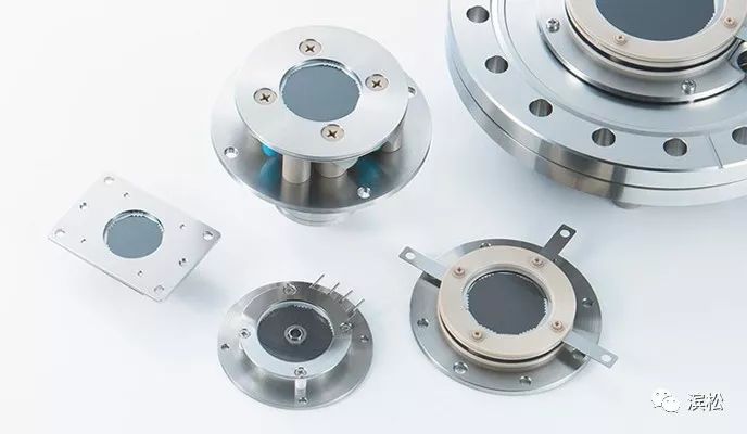
Hamamatsu MCP products
Microchannel Plate (MCP) can be used to detect various particles and high-energy electromagnetic waves such as electrons, ions, high-energy particles, neutrons, ultraviolet light, and X-rays. It is a plate-like structure made up of a large number of hollow capillary tubes (microchannels) arranged in two dimensions (see Figure 1-A, B).
The inner walls of the microchannels are treated to generate secondary electrons when particles strike. During use, a voltage is applied across the MCP, creating an electric field inside the microchannels. The secondary electrons generated by particle impacts are accelerated by the electric field, causing them to strike the inner walls of the microchannels again, producing more secondary electrons (as shown in Figure 1-C). This process repeats multiple times within the same microchannel, ultimately resulting in a large number of electrons being output at the exit (referred to as multiplied electrons).
The ratio of the multiplied electrons output by the MCP to the number of incident particles is known as the MCP gain, which is typically around 103 for a single MCP.
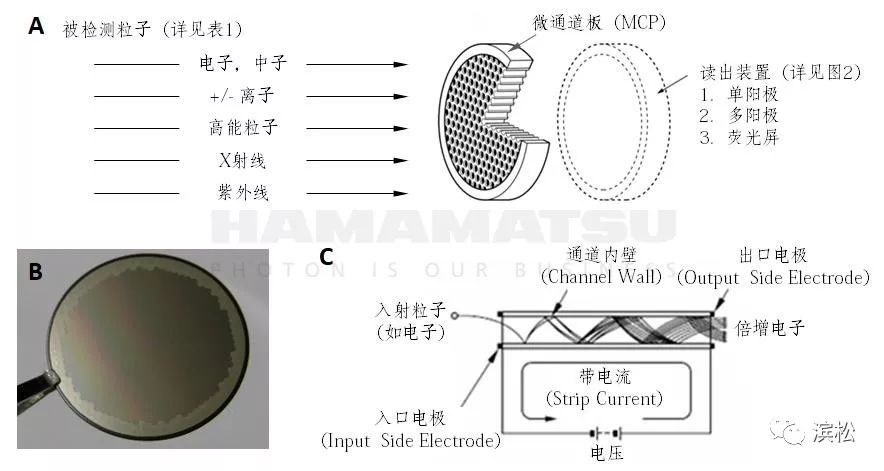
Figure 1. MCP Structure and Basic Principles
The size of MCPs generally ranges from 10-100mm, with a thickness of about 0.5-1mm and a microchannel diameter of around 10um.
There are generally three readout methods for the multiplied electrons output by MCP: single anode readout, multi-anode readout, and phosphor screen readout. Hamamatsu can provide not only bare MCPs but also module products corresponding to various signal readout methods and requirements.
· Single Anode Readout Module: All multiplied electrons output from the MCP are received by the same anode, converting them into an electrical signal. This type of module acts as a point detector and is commonly used as a mass spectrometer detector;
· Multi-Anode Readout Module: The multiplied electrons output from different positions of the MCP correspond to different anodes, giving this type of module position discrimination capability, which can be used in applications such as chemical analysis with electron spectroscopy (ESCA). Multi-anodes can be arranged linearly or in two dimensions (see Figure 2). The anode pitch can be 3mm or more;
· Phosphor Screen Readout Module: The phosphor screen can convert the electrons output from the MCP into visible light. When used with a single MCP, the resolution can reach 40-50um; when used with two MCPs, the resolution can achieve 80-100um. Depending on different requirements (such as the color of the output visible light, phosphorescent decay time, response time, etc.), different phosphor screens can be selected.
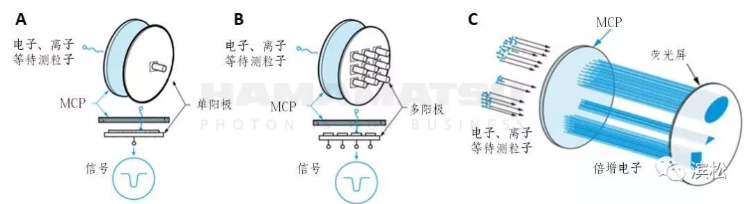
Figure 2. Schematic of MCP Readout Modules: (A) Single Anode Readout; (B) Multi-Anode Readout; (C) Phosphor Screen Readout
MCPs have been widely used in mass spectrometry, electron microscopy, surface analysis, etc. For example, in mass spectrometry applications, samples are ionized in the ion source, and after passing through the mass analyzer, ions with different mass-to-charge ratios (m/z, i.e., charge/molecular weight) are separated and fly towards the MCP in a vacuum, ultimately being detected by the MCP.
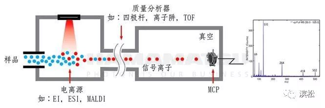
Figure 3. Schematic of MCP Usage in Mass Spectrometry
Analysis of 5 Important Parameters
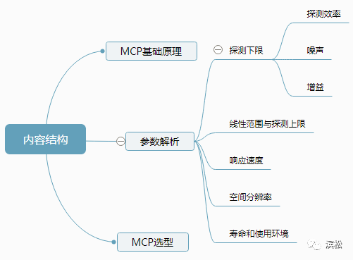
As a type of detector, the MCP’s detection limit, detection upper limit, linear range, response speed, lifespan, and operating environment are frequently focused characteristics. Additionally, for MCP modules with phosphor screen output, spatial resolution is also very important. Next, we will analyze these features.
Detection Limit
◆ ◆ ◆
The core of the detection limit is the signal-to-noise ratio of the entire detection system.
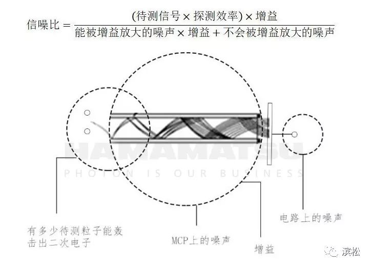
Figure 4. Parameters Related to MCP Signal-to-Noise Ratio
To achieve a better detection limit, we can approach it from the following three aspects:
Improve detection efficiency;
Reduce noise, especially noise that can be amplified by gain;
Enhance gain.
When the MCP detects weak signals, the higher the proportion of the signal being measured that can be received and cause secondary electrons to be emitted (i.e., the higher the detection efficiency), the better it can “utilize” the signal being measured, leading to a lower detection limit.
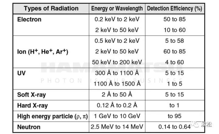
Different particles/electromagnetic waves have different detection efficiencies in the MCP (see Table 1), so the first strategy to improve MCP detection efficiency is to convert particles/electromagnetic waves with low detection efficiency to particles with high detection efficiency (e.g., electrons).
For example, (a) the MCP has a relatively low detection efficiency for VUV; in VUV detection, a photoelectric conversion material such as CsI can be coated on the MCP entrance to convert VUV to electrons; (b) the MCP has almost no response to visible light; in ultra-weak visible light detection, a photoelectric material such as GaAs can be used to convert visible light to electrons.
Table 1. MCP Detection Efficiency for Various Particles/Electromagnetic Waves
The second strategy to improve detection efficiency is to ensure that a larger proportion of incident particles successfully cause secondary electrons to be emitted. There are two specific methods:
# Increase Open Area Ratio (OAR)
The open area ratio refers to the “MCP surface microchannel opening area / total effective area of the MCP.” The higher the open area ratio, the higher the detection efficiency of the MCP. Typically, the open area ratio of ordinary MCPs is 60%, while the funnel-type MCP developed by Hamamatsu can reach an open area ratio of 90% (see Figure 5, actual comparison in Figure 6).
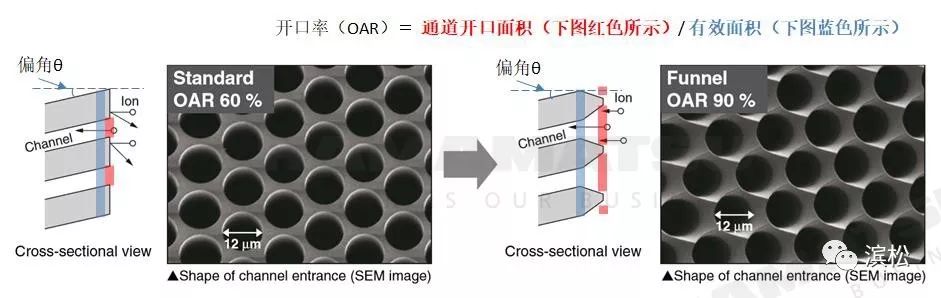
Figure 5. MCP Open Area Ratio and Bias Angle
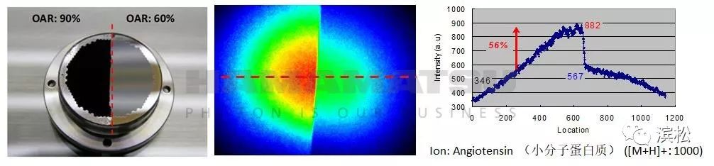
Figure 6. Comparison of MCP Detection Efficiency with Different OARs
The sample is a small molecule protein, and the detection system is MALDI-TOF.
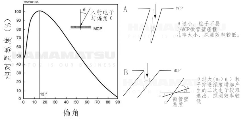
# Choose an Appropriate Bias Angle
The bias angle refers to the angle between the microchannel and the normal to the MCP surface, allowing particles a greater probability of striking the inner walls of the microchannels (see Figure 5). However, a larger bias angle is not always better; for electrons, for example, after entering the inner wall of the microchannel and generating secondary electrons, the location of secondary electron generation is related to the bias angle. If the bias angle is too large, causing the secondary electrons to be generated deeper within the microchannel, it can reduce the emission of secondary electrons; if the bias angle is too small, it may not generate enough secondary electrons. The typical bias angle for MCPs is 8° to 12°.
In the detection system involving the MCP, noise can be divided into noise from the MCP itself and noise from the readout end.
The noise from the MCP itself is relatively low; at a voltage of 1000V, the dark current of a single MCP is below 0.5pA/cm2. In comparison, photomultiplier tubes (PMTs) are known for their high signal-to-noise ratios; Hamamatsu’s R928 side-window photomultiplier tube has a photosensitive area of 8mm x 24mm = 1.92 cm2, with a typical dark noise value of 3nA, equivalent to about 1500pA/cm2.
The main noise source to consider in MCP usage is ion feedback (Ion Feedback, specific mechanism shown in Figure 7). Although the MCP operates in a vacuum, there are always residual gas molecules. When the multiplied electrons output from the MCP collide with residual gas molecules, positive ions are generated. These positive ions will move in the opposite direction to the multiplied electrons in the electric field, striking the inner walls of the microchannels again to produce electrons; this process is known as ion feedback. Since the reverse motion of positive ions takes time, the signals produced by ion feedback do not overlap with the actual signals, but rather become a significant source of noise.
Therefore, when the vacuum level is insufficient, excessive residual gas molecules can lead to additional noise during actual use, which is particularly noteworthy. For Hamamatsu’s MCP products, it is recommended to operate below 1.3×10⁻⁴Pa. However, Hamamatsu will soon release MCP modules capable of operating under low vacuum conditions (down to 1Pa), so stay tuned.
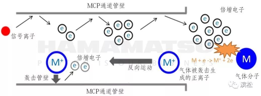
Figure 7. Schematic of Ion Feedback
Due to the low noise from the MCP itself, noise introduced at the readout end (mainly noise that cannot be amplified by MCP gain, refer to the formula in Figure 4) can have a significant impact. Specifically, whether in the readout circuit of the single anode output mode or in the phosphor screen output mode with the phosphor screen + camera, additional noise will be introduced.
Therefore, when detecting weak signals, using a higher gain for the MCP not only amplifies the signal and generates more multiplied electrons but also improves the overall signal-to-noise ratio of the system.
The gain of the MCP is mainly related to the aspect ratio (α) and voltage. The aspect ratio refers to the ratio of the length to the diameter of the microchannels (see Figure 8); the voltage refers specifically to the voltage applied across the MCP (as shown in the voltage in Figure 1-C). As shown in Figure 8, the larger the aspect ratio, the greater the gain provided by the MCP; the higher the voltage applied across the same MCP, the greater the gain.
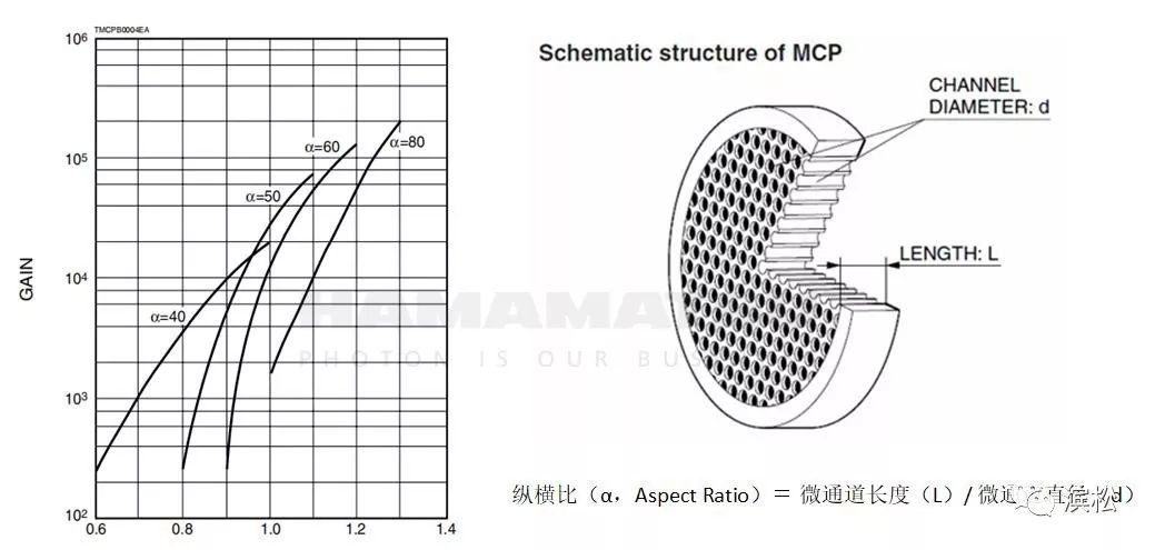
Figure 8. Relationship Between MCP Gain, Voltage, and Aspect Ratio
For a single MCP, when the gain exceeds 104, the quantity of multiplied electrons emitted from the MCP increases, and the noise generated by ion feedback becomes significant; thus, a high aspect ratio is generally not used (typically 40-60, allowing for a gain of 104 at a voltage of 1kV).
If higher gain is required in applications, it is common to stack 2-3 MCPs together and reverse the bias angles of the front and back MCPs (see Figure 9). This reverse angle design makes it difficult for feedback ions to enter the first MCP, effectively reducing ion feedback and improving the signal-to-noise ratio. As shown in Figure 9, the gain of 2-3 stacked MCPs is generally higher. In practical use, it is most common to stack two MCPs together to achieve a gain of over 106.
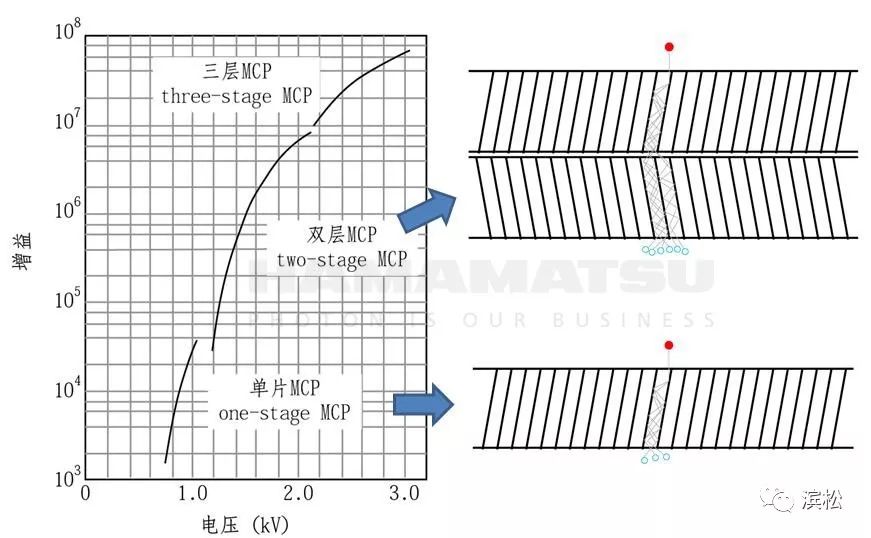
Figure 9. Usage Scheme and Effects of Stacking 2-3 MCPs Together
In summary, as long as the required high vacuum environment is maintained, the noise from the MCP itself is very low. If there is a particular focus on detecting weak signals, when selecting and using, the following can be considered:
1)Select models with large open area ratios (OAR) to ensure high detection efficiency;
2)Appropriately use higher voltages and choose to stack 2-3 MCPs together to achieve higher gain, indirectly suppressing noise at the readout end and reducing the difficulty of signal readout.
Linear Range and Detection Upper Limit
◆ ◆ ◆
The linear range depends on the difference between the detection upper limit and the detection lower limit. If a method (such as reducing gain) increases both the detection upper limit and the detection lower limit, it often does not enhance the dynamic range. Since the detection lower limit of the MCP is closely related to gain (see the previous section), when hoping for a large linear range from the MCP, the main consideration is how to increase the detection upper limit without affecting gain.
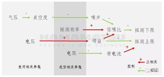
Figure 10. Parameter Analysis of MCP Detection Upper Limit and Detection Lower Limit
The main parameter related to the MCP detection upper limit is called Maximum Linear Output Current, which typically has an absolute value of 3-5uA.
When the number of output electrons from the MCP increases, the inner walls of the MCP become charged due to the large number of secondary electron emissions, which affects the electric field distribution and weakens the subsequent multiplication process. The charge on the inner walls of the MCP is neutralized by the strip current (refer to Figure 1-C). However, due to the high equivalent internal resistance of the MCP (generally 100-1000MΩ), the strip current is usually small, leading to residual charge on the microchannel walls that cannot be neutralized in time when the number of multiplied electrons is excessive, affecting the electric field distribution within the MCP and ultimately causing a decrease in gain—at this point, the MCP’s response to signal ions is no longer linear.
Since the maximum linear output current of the MCP is related to the size of the strip current, it is sometimes marked as a percentage of the strip current, such as “7% of strip current.”
Based on the principles above, to increase the maximum linear output current and achieve a larger linear range, the first strategy is to use an MCP with lower equivalent internal resistance (like the 2-30MΩ used in Hamamatsu’s F6584); at the same voltage, a lower resistance can achieve a larger strip current, thereby enhancing maximum linear output and linear range (see Figure 11).
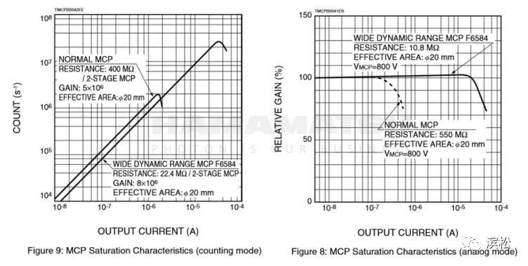
Figure 11. Large Linear Range and High Maximum Linear Output of Low Resistance MCP
In addition, Hamamatsu also provides the second strategy, which is to use one MCP in conjunction with an avalanche diode (Avalanche Diode) (the “MCP+AD” module), thereby achieving a higher linear range and maximum linear output.
In this combination, the overall gain of the module is still around 106, similar to the gain of two MCPs used together—meaning the detection limit is not compromised. However, the gain of the MCP part is only 1000-10000, which is 2-3 orders of magnitude lower than the 106 gain of two MCPs used together, meaning that multiplied electrons are much fewer, allowing for the acceptance of more particles to be measured before reaching the maximum linear output current of the MCP—thereby achieving a higher detection upper limit. Therefore, the “MCP+AD” module can achieve a linear range and detection upper limit far exceeding that of traditional MCP modules.
From a parameter perspective, the maximum linear output current of the MCP+AD module can reach up to 230uA, far exceeding the 3-5uA of the MCP. At the same time, since the number of multiplied electrons in the MCP+AD module is less than in the case of using two MCPs together, the overall lifespan of the module is also extended. (We will release detailed information about this product soon, so stay tuned to Hamamatsu China’s public account~)
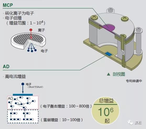
Figure 12. Schematic of Hamamatsu MCP+AD Module
In summary, if you want the MCP detection system to have a larger linear range, you can mainly consider:
1)Select models with lower resistance, such as Hamamatsu F6584;
2)Select MCP+AD module products.
Response Speed
◆ ◆ ◆
When a particle to be measured strikes and emits secondary electrons, the flight paths of each multiplied electron are not identical, causing the time taken for electrons to reach the anode (taking the single anode readout MCP module as an example) to vary, resulting in a certain peak width in the signal. As the total flight distance increases, the flight distances among the multiplied electrons also diverge, leading to a noticeable widening of the signal peak and an increase in the rise time of the signal when using a single anode readout MCP module.
However, overall, the response speed of the MCP is very fast, with a rise time typically between 0.3-1.5ns. In contrast, another type of particle detector—the electron multiplier—has a rise time typically between 1-5ns.
The response speed of the MCP is mainly related to the length of the microchannels. The longer the length, the greater the flight distance of the electrons, and thus the longer the rise time of the signal.
Since the gain of the MCP does not solely depend on the length of the microchannels but also on the aspect ratio (equal to the length/diameter of the microchannels), the first strategy to enhance response speed is to proportionally reduce the length and diameter of the MCP microchannels, which can increase response speed without diminishing gain (such as Hamamatsu F4655-13).
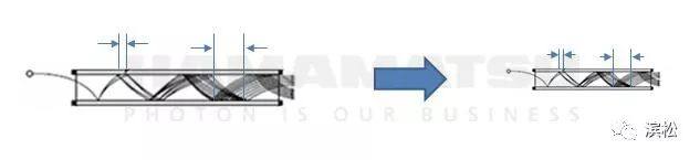
Figure 13. Strategies to Increase MCP Response Speed
Proportionally reducing the length and diameter of the MCP microchannels
In addition to the length of the MCP microchannels, the multiplied electrons flying from the MCP exit to the anode or phosphor screen are also distributed at a certain angle. Electrons flying directly toward the anode and those at an angle will have different arrival times at the anode, so the second strategy to enhance response speed is to add additional mesh electrodes between the MCP exit and the anode, correcting the flight paths of the multiplied electrons to make their flight distances more uniform.
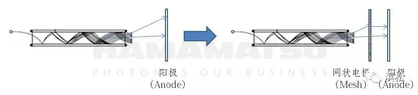
Figure 14. Strategies to Increase MCP Response Speed
Correcting the flight paths of multiplied electrons
Spatial Resolution
◆ ◆ ◆
When the MCP is used in conjunction with a phosphor screen, spatial resolution is also a very important parameter. The resolution can reach 40-50um when a single MCP is used with a phosphor screen; when two MCPs are stacked, the resolution can typically achieve 80-100um.
Using two MCPs will decrease the resolution compared to using one MCP because: (1) electrons coming out of one microchannel in the first MCP may enter multiple channels in the second MCP; (2) the number of multiplied electrons output from two MCPs will be higher, and mutual exclusion among electrons will increase the exit angle, reducing resolution (see Figure 15).
To increase spatial resolution, consider:
1)Shorten the distance between the MCP and the phosphor screen; although mutual exclusion among electrons will increase the exit angle in the microchannels, shortening the distance can mitigate its impact on spatial resolution;
2)Increase the acceleration voltage between the MCP and the phosphor screen.
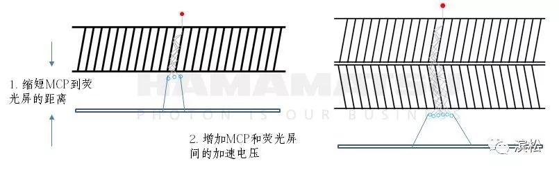
Figure 15. Factors Affecting Spatial Resolution When Using MCP with Phosphor Screen
Lifespan and Operating Environment
◆ ◆ ◆
The lifespan of the MCP is related to the total number of electrons emitted from it, so the lifespan of the MCP is expressed in terms of charge. Generally, the lifespan of the MCP is 10C (Coulombs) or more. In comparison, the lifespan of electron multipliers, which are also particle detectors, is only 0.3C (total charge quantity).
Additionally, at the same voltage, the gain of the MCP decreases with use, so when the signal is not too weak, Hamamatsu recommends that for a new MCP, the voltage can be set lower than that in the parameter table, so that the multiplied electrons emitted from the MCP are not too many, which helps extend the lifespan of the MCP. Moreover, as usage progresses, the voltage on the MCP can be gradually increased to maintain stable gain.
In terms of operating environment for the MCP, two parameters generally need to be monitored:
# Magnetic Field
The MCP is less sensitive to magnetic fields compared to PMTs and electron multipliers. However, magnetic fields can still affect the MCP, especially when perpendicular to the microchannels. If the MCP must be used in a magnetic field environment, try to align the magnetic field parallel to the long axis of the microchannels. Selecting appropriate MCPs and orientations can allow the MCP to operate normally in a magnetic field of 2T.
# Vacuum Level
Ordinary MCPs have high vacuum requirements, needing to operate below 1.3×10⁻⁴Pa. In low vacuum conditions (i.e., when the pressure is relatively high), more gas molecules can be ionized, which not only leads to high noise due to the principle of ion feedback (see Figure 7), but also these additional multiplied electrons (which are essentially noise) will reduce the lifespan of the MCP.
However, for certain applications, maintaining a high vacuum level is not possible. In response to this situation, Hamamatsu has specifically developed an MCP module that can operate at a vacuum level of 1Pa (Gen3 three-tier structure MCP), which will be released soon.
MCP Selection Reference
Including MCPs, Hamamatsu offers various particle detectors. Relatively speaking, MCPs have the following advantages:
1)MCPs have a large detection area, generally ranging from 10mm to 100mm, containing millions of microchannels;
2)The failure of a single microchannel does not affect overall usage, so the lifespan of MCPs is greatly superior to that of EMs and CEMs (reflected in a longer accumulated charge lifespan);
3)Due to the relatively short length of microchannels in MCPs, the flight distance of electrons is shorter, so the time response of MCPs is faster than that of EMs and CEMs (reflected in shorter rise times).
However, MCPs also have their shortcomings, such as a narrower dynamic range (reflected in maximum output current). This can be understood as the small potential difference between the stages in the MCP, which limits the number of electrons that can be driven to the maximum output current, resulting in a low ceiling for maximum output current. To address this issue, Hamamatsu has developed theMCP+AD module (as introduced above).
Additionally, to meet the high vacuum requirements, the upcomingGen3 three-tier structure MCP will also greatly address this issue.
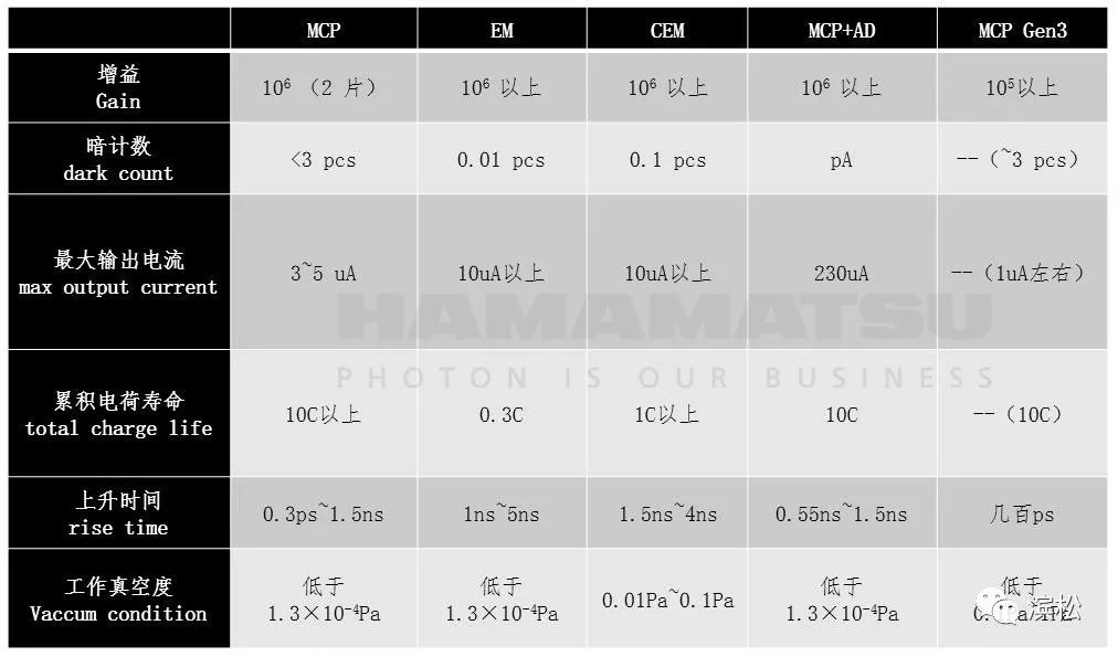
Table 2. Comparison of Various Particle Detectors
For more information on Hamamatsu’s MCP selection manual and related materials, please follow Hamamatsu’s public WeChat account, reply “MCP” to obtain.
That’s all for our introduction to MCP. If you want to learn more about MCP products, technologies, and usage, feel free to leave a message below the article. We will successively launch several new MCP products (as mentioned above), so please continue to follow us~
Content provided by


Editor: Hamamatsu Editor

Editor Portal
More exciting content
Pre-treatment time is only 1/10 of MALDI; this little thing is also impressive!
Should VOC monitoring start from the “head”? What does that mean?
Hamamatsu focuses on promoting new products such as ion sources and detectors in the mass spectrometry field
Overview of the family of photomultiplier tubes, so they all have it…
Is selecting a photodiode (PD) difficult? Here’s a complete parameter analysis!