This tutorial introduces the modeling and analysis methods for cylindrical shell structures in ABAQUS through a case study of a wind turbine tower. By studying this case, readers will master the following key points:
☆ Master the use of Boolean operations;
☆ How to use sketch curves;
☆ Master the structural eigenvalue buckling analysis method.
1. Case Description
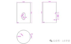
Use ABAQUS software to establish the model of the wind turbine tower and door opening, and perform buckling and load-bearing capacity analysis of the structure. The tower is made of Q345 steel, and specific dimensions are shown in Figure 1.1.
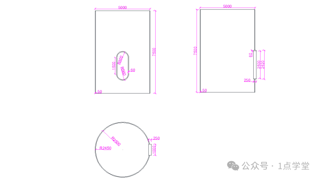
Figure 1.1 Dimensions of the Wind Turbine Tower (Unit: mm)
2. Creating Components
In the environment bar of the user interface, the module list defaults to the Part module, as shown in Figure 1.2. In this module, the geometric shapes of various parts can be defined.

Figure 1.2 Part Module
(1) Creating the Tower Component
 Select Component Type
Click the  Create Part button to open the Create Part dialog box, as shown in Figure 1.3. In the Name field, enter the name [Tower]; check the 3D checkbox in the Modeling Space field; check the Deformable checkbox in the Type field; set the Base Feature under Shape to Solid, Type to Extrusion; enter [10000] in the Approximate size field; click Continue… to enter the sketching interface.
 Sketching the Component
In the sketching interface, click the  Create Circle button, and in the prompt area, enter the coordinates of the circle center (0, 0), press Enter, and then enter the radius of the circle (2500, 0) to complete the outer circle sketch of the tower. Click the
  Create Circle button again, enter the coordinates of the tower center (0, 0), press Enter, and then enter the radius of the circle (2450, 0), press Enter to complete the inner circle sketch of the tower. The completed sketch is shown in Figure 1.4. After the sketch lines are drawn, click the middle mouse button or the Done button in the prompt area to finish drawing the sketch.
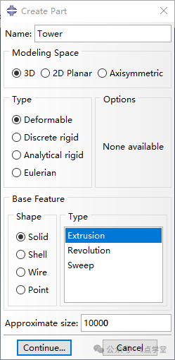
Figure 1.3 Create Part Dialog Box
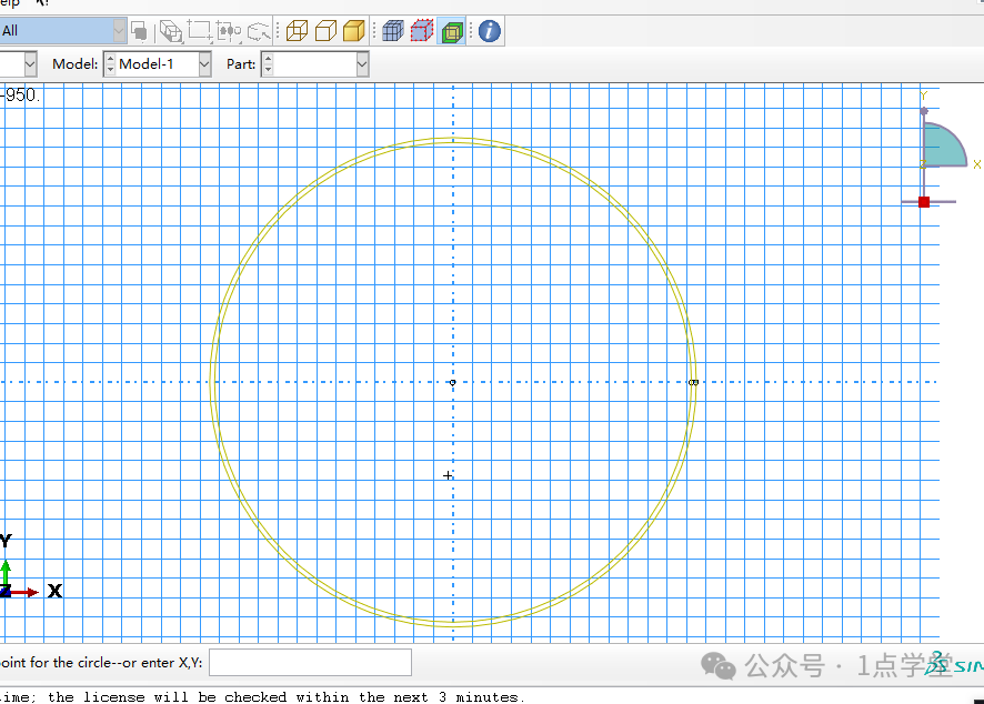
Figure 1.4 Sketch Drawing Section
 Extrusion of Solid Component
Open the Edit Base Extrusion dialog box, enter [7500] in the Depth field under End Condition, as shown in Figure 1.5, click OK to close the Edit Base Extrusion dialog box, completing the establishment of the tower model, as shown in Figure 1.6.
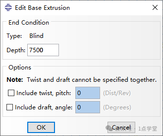
Figure 1.5 Edit Base Extrusion Dialog Box
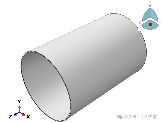
Figure 1.6 Tower Model
(2) Creating the Door Opening Component
In the tool area, click the  Create Part tool to open the Create Part dialog box, enter the component name [Door], keep other options as default, click Continue to open the sketching interface, click
  , enter coordinates (0,0), press Enter, then enter coordinates (1120,1500), press Enter to complete the rectangle drawing, then click
  Create Arc:Tangent to Adjacent Curve, select the two points on the top and bottom of the rectangle to draw two semicircles. Click Auto Trim, and click the top and bottom sides of the rectangle to trim them. Click Save Sketch As, enter the sketch name [Sketch-Door] in the prompt area, press Enter to save the sketch for later use. Click
  , enter coordinates (60,0), press Enter, then enter coordinates (1060,1500), press Enter to complete the rectangle drawing, then click
  to select the two points on the top and bottom of the rectangle to draw two semicircles. Click, click the top and bottom sides of the rectangle to trim them. The completed door opening sketch is shown in Figure 1.7. After finishing the sketch drawing, click the middle mouse button; in the End Condition field, enter [250] in the Depth field to form the door frame component, as shown in Figure 1.8.

Figure 1.7 Door Opening Sketch
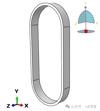
Figure 1.8 Door Opening Component
(3) Creating the Door Cutting Component
In the tool area, click the Create Part tool to open the Create Part dialog box, enter the component name [Door-Cut], keep other options as default, click Continue to open the sketching interface. In the tool area, click  Add Sketch, select the previously saved Sketch Door sketch in the opened Select Sketch dialog, click the middle mouse button (twice), open the End Condition dialog, enter [1000] in the Depth field, click OK to complete the creation of the cutting component, as shown in Figure 1.9.
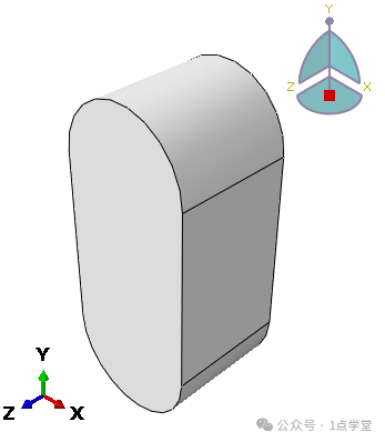
Figure 1.9 Cutting Component
3. Assembly of Instances
(1) Assembly of the Tower and Boolean Operations
 Import the Tower and Cutting Components
Select the Assembly module in the Module, click the Create Instance button in the left tool area to open the Create Instance dialog box, as shown in Figure 1.10. Hold down the Shift key, select both Tower and Door-Cut components, select Dependent for the instance type, check Auto-offset from other instances to prevent component overlap, and click OK to import the Tower and Door-Cut components into the view window.
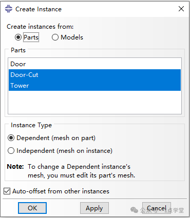
Figure 1.10 Create Instance Dialog Box
 Create Datum Point and Component Offset
In the toolbar, click  Create Datum Point: Midway Between 2 Points, click the upper and lower points on the outer side of the Tower component to create the first datum point, then click the upper points of the Door-Cut component to create the second datum point, as shown in Figure 1.11. In the tool area, click
  Rotate Instance, select the Door-Cut component in the view window, click the middle mouse button, enter the coordinates (0,0,0) in the prompt area, press Enter, then enter the coordinates (1,0,0), press Enter, and enter 90 for the Angle of rotation, press Enter to rotate the Door-Cut around the X-axis by 90 degrees. Click
  Rotate Instance, select the Tower-Cut component, click the middle mouse button, enter the coordinates (0,0,0), press Enter, then enter the coordinates (0,0,1), press Enter, and enter 90 for the Angle of rotation to rotate the Tower-Cut around the Z-axis by 90 degrees.
Click Translate Instance, select the Door-Cut component in the view window, click the middle mouse button, first select datum point 1, then select datum point 2 to move the Door-Cut component to the door opening position of the Tower component, as shown in Figure 1.12.
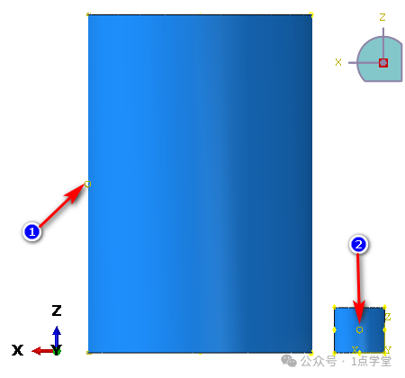
Figure 1.11 Creation of Datum Points
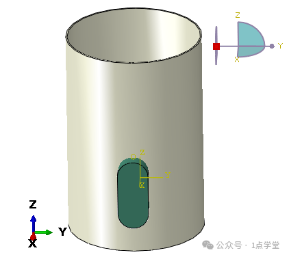
Figure 1.12 Instance After Offset Completion
 Boolean Operations
Click  to open the Merge/Cut Instances dialog box, enter the component name [Tower-Cut], select Cut geometry for Operations, select Suppress for Options, click Continue, and in the view window, use the mouse to select the Tower component as the component to be cut, click the middle mouse button, then select the Door-Cut component to cut the Tower, completing the example of Boolean operations as shown in Figure 1.14.
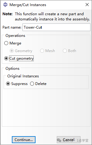
Figure 1.13 Merge/Cut Instances Dialog Box
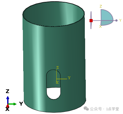
Figure 1.14 Completed Cut Tower Component
(2) Assembly of the Door Opening Component
 Import the Door Frame Component
In the tool area, click  to open the Create Instance dialog, select the Door component, keep other options unchanged, and click OK to import the Door component into the assembly instance.
 Rotate the Door Component
In the tool area, click  Rotate Instance, select the Door component in the view window, click the middle mouse button, enter (0,0,0) in the prompt box, press Enter, then enter (1,0,0) and press Enter, and enter 90 degrees for the Angle of rotation to rotate the Door component around the X-axis by 90 degrees. Click
  Rotate Instance, select the Door component in the view window, click the middle mouse button, enter (0,0,0) in the prompt box, press Enter, then enter (0,0,1) and press Enter, and enter 90 degrees for the Angle of rotation to rotate the Door component around the Z-axis by 90 degrees.
 Creation of Datum Points and Component Offset
In the toolbar, click  to create the first datum point by clicking the inner and outer walls of the Tower-Cut component, then click the upper points of the Door component to create the second datum point, as shown in Figure 1.15. In the tool area, click in the view window to select the Door component, click the middle mouse button, and use the mouse to select datum point 2, then click datum point 1 of the Tower-Cut component, click the middle mouse button to complete the offset of the door frame component.
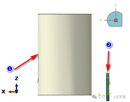
Figure 1.15 Creation of Datum Points
 Boolean Operations
Click  to open the Merge/Cut Instances dialog box, enter the component name [Tower+Door], select Merge for Operations, select Suppress for Options, select Remove for Geometry, as shown in Figure 1.16, click Continue, and in the view window, use the mouse to select all components, click the middle mouse button to merge the tower and door frame into a whole.

Figure 1.16 Column 2 Array Copy Dialog Box
4. Input and Assignment of Material Properties
 Input of Steel Density
Click  to open the Create Material dialog box, enter the material name as “Q345”, click General→Density→Mass Density to input the density of Q345 steel as “7.85e-9”, and click OK;
 Input of Steel Elastic-Plastic Parameters
In the Edit Material dialog, click Mechanical→Elasticity→Elastic, enter “2e6” in Young’s Modulus, enter “0.28” in Poisson’s Ratio, click OK to complete the input of steel material properties. Then click Mechanical→Plasticity→Plastic, input the stress-strain data of steel, as shown in Figure 1.17. Click OK to complete the input of steel material properties.

Figure 1.17 Plastic Parameters of Q345 Steel
(2) Material Assignment
In the left tool area, click  Create Section, open the Create Section dialog box, as shown in Figure 1.20a, enter the section name as [Q345], select Solid for Category, select Homogeneous for Type, click Continue to open the Edit Section dialog box, select Q345 material from the material dropdown menu, click OK to complete the definition of the tower section.
Switch the Module from Part to Tower+Door, click  Assign Section, then in the view window, use the mouse to select the tower component (if you do not need to create a set, you can uncheck the Create Part option in the operation prompt area), after selecting, click the middle mouse button to open the Edit Section Assignment dialog box, select Q345 section in the Section field, click OK, and the component will change from gray to cyan-green, indicating that the material assignment was successful.
5. Mesh Division of the Model
 Creating Component Partition
Select the Mesh module in the Module, select Part for Object, and first select the Tower+Door component. Due to the door frame, the component is irregular, and it cannot be directly divided into hexahedral elements, so partitioning operations must be performed on the entire component first. In the tool area, click  Partition Cell: Define Cutting Plane, in the operation prompt area, select
  , at this time, in the view window, select the center of the top circle of the tower, then select the line parallel to the X-axis inside the door frame, as shown in Figure 1.19. Click Create Partition in the prompt area to complete the first partition. Then click
 Partition Cell: Extend Face, using the top and bottom semicircular surfaces and the left and right rectangular surfaces of the door frame as the extending surfaces to cut the connection between the door frame and the tower, ultimately turning all structures yellow and green.
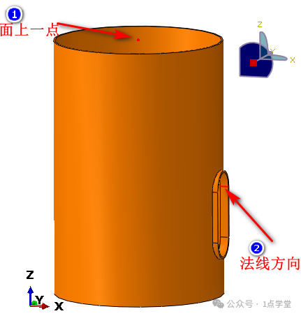
Figure 1.18 Partition Point and Normal Selection
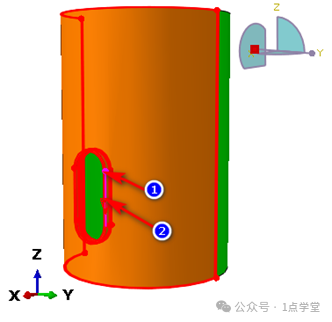
Figure 1.19 Point Partition Two Points and Normal Selection
 Mesh Division of the Tower Component
In the left tool area, click  Assign Mesh Controls, in the view area, select the entire component, click the middle mouse button to open the Mesh Controls dialog box, as shown in Figure 1.20. In the Technique field, check Sweep, select Medial axis for Algorithm, and click OK. Click
  Seed Part to open the Global Seeds dialog box, as shown in Figure 1.21, enter “95” in the Approximate global size field, keep other options unchanged, and click OK to complete the seed layout. In the tool area, click
Figure 1.20 Mesh Controls Dialog Box
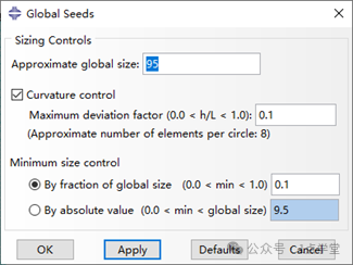
Figure 1.21 Global Seeds Dialog Box
6. Creation of Eigenvalue Buckling Analysis Steps
 Analysis Step Settings
Select the Step module in the Module, click Create Step to open the Create Step dialog box as shown in Figure 1.22a, enter the analysis step name as “Buckle Analysis”, select Linear perturbation for Procedure type, then select Buckle, click Continue, and in the Edit Step dialog, check Lanczos in the Eigensolver field, enter “10” in the Number of eigenvalues requested field, as shown in Figure 1.22b, click OK to complete the analysis step settings.
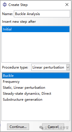
(a) Create Step Dialog Box
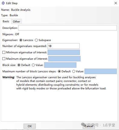
(b) Edit Step Dialog Box
Figure 1.22 Buckle Analysis Step Settings
 Field Variable Output Settings
Click the Field Output Manager dialog box in the toolbar to open the Field Output Requests Manager dialog box, click Edit to check the data to be output for the calculation, as shown in Figure 1.23. In this example, select to output S and U.
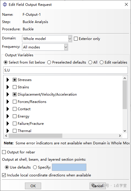
Figure 1.23 Field Output Manager Dialog Box
7. Boundary Conditions and Load Settings
 Boundary Condition Settings for the Bottom of the Tower
Select the Load module in the Module, click Create Boundary Condition to open the Create Boundary Condition dialog box, as shown in Figure 1.24a, enter the first boundary condition as BC-Bottom, select Initial for Step, select Symmetry/Antisymmetry/Encastre, click Continue, hold down the Shift key, and use the mouse to click all the surfaces at the bottom of the tower in the view window, click the middle mouse button, and in the Edit Boundary Condition dialog box as shown in Figure 1.24b, check ENCASTRE(U1=U2=U3=UR1=UR2=UR3=0), click OK to complete the boundary condition settings for the bottom of the tower.
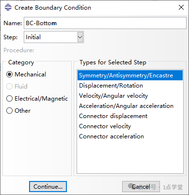
(a) Create Boundary Condition Dialog Box
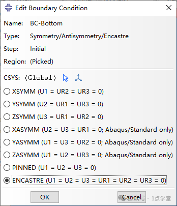
(b) Edit Boundary Condition Dialog Box
Figure 1.24 Boundary Condition Settings for the Bottom
 Boundary Condition Settings for the Top of the Tower
In the tool area, click  to open the Create Boundary Condition dialog box, enter the boundary condition name as BC-Top, select Initial for Step, select Displacement/Rotation, click Continue, hold down the Shift key, use the mouse to click all surfaces at the top of the tower, in the bottom prompt area Select regions for the boundary condition, check Create Set, enter the name BC-Top, click Done, open the Edit Boundary Condition dialog box, check U1, U2, and click OK to complete the boundary condition settings for the top of the tower.

Click the tool area  Create Load tool to open the Create Load dialog box, as shown in Figure 1.25. Select Buckle Analysis for Step, select Pressure for Types for Selected Step, click Continue to open the Edit Load dialog box, as shown in Figure 1.25b. Enter the pressure value of 1000 at the top of the tower, with the unit being MPa.
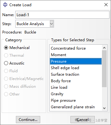
Figure 1.25a Create Load Dialog Box
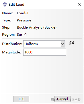
Figure 1.26b Edit Load Dialog Box
8. Job Creation and Submission
 Create Job
Select the Job module, click  Create job, open the Create job dialog box as shown in Figure 1.26a, enter the job name as Job-Buckle Analysis, select the calculation model Model-1, click Continue to open the Edit job dialog box, as shown in Figure 1.26b. In the Parallelization menu of the Edit job dialog box, check Use multiple processors, fill in the actual number of threads of the computer in the data frame, in this example, fill in 4, and click OK.

Figure 1.26a Create Job Dialog Box
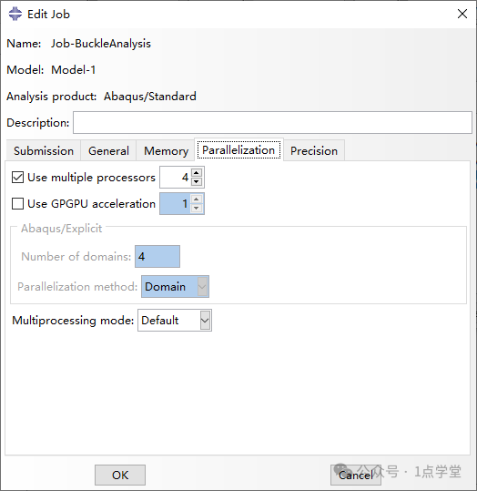
Figure 1.26b Edit Job Dialog Box
 Submit the Calculation
In the left tool area, click  Job Manager to open the Job Manager dialog box, click Submit to submit the job for calculation. Monitor can be used to view the calculation progress, and when the Status changes to Completed, it indicates that the calculation is complete. Click Results to enter post-processing and view the results.
9. Result Viewing
In the left tool area, click  Plot Contours on Deformed Shape to display the structural contour plot in the view window. By clicking the toolbar,
  you can view the structural deformation contour plots under different eigenvalues. Figure 1.27 shows the stress and displacement contour plots of the structure at the first eigenvalue.
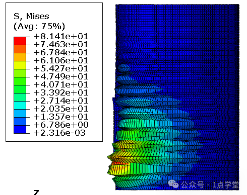
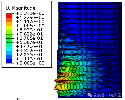
Figure 1.27 Stress and Displacement Contour Plots at First Eigenvalue
1 Point Teacher Class Area & Special Benefits
1. Overview of 1 Point Teacher Courses
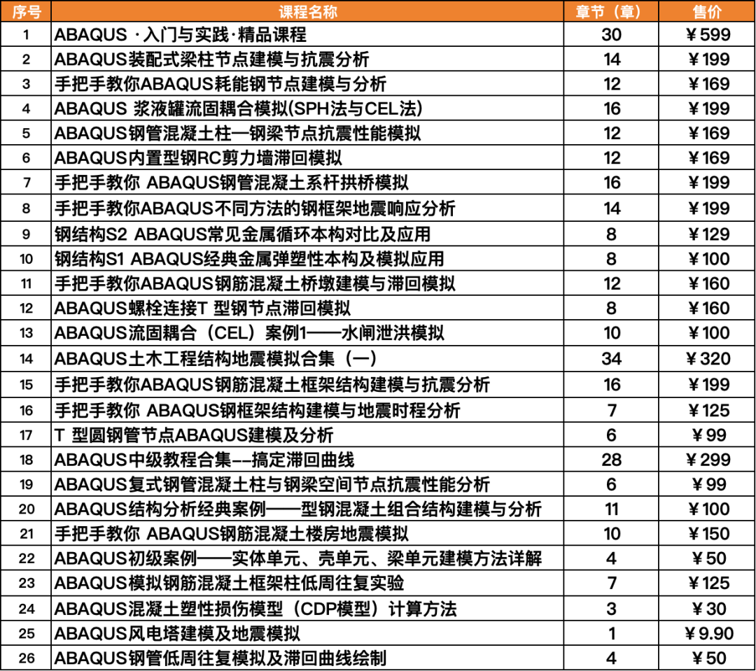
Currently, 1 Point Teacher has published a total of 26 courses on the Technical Neighbor platform, covering all stages of ABAQUS from basic to advanced. Through various case practices, it helps everyone master the application of ABAQUS in work. (For course details, please click “Read more” at the end)
2. Special Benefits for 1 Point Teacher Courses
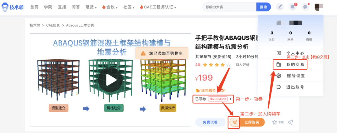
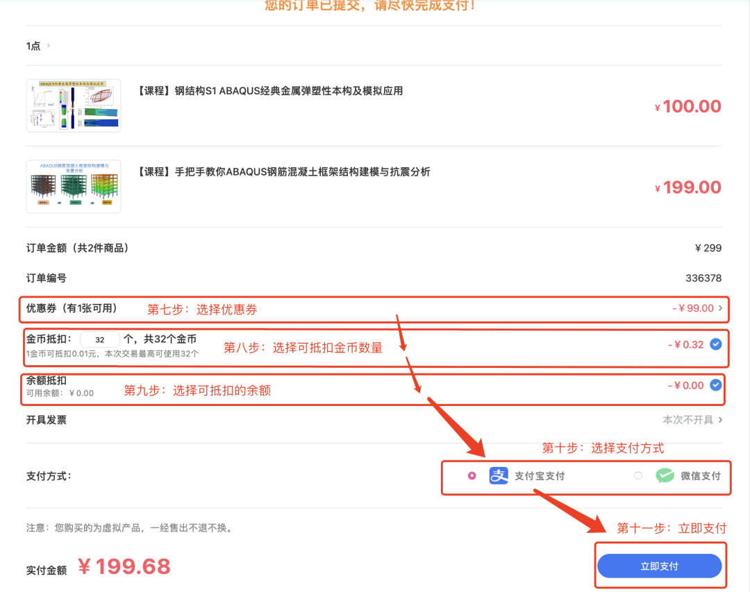
All courses of 1 Point Teacher participate in the299 yuan discount of 99 yuan activity, limited time and quantity, hurry up to receive!

*Note: 1. Courses with amounts greater than 299 yuan can directly receive a discount coupon, click to buy now.
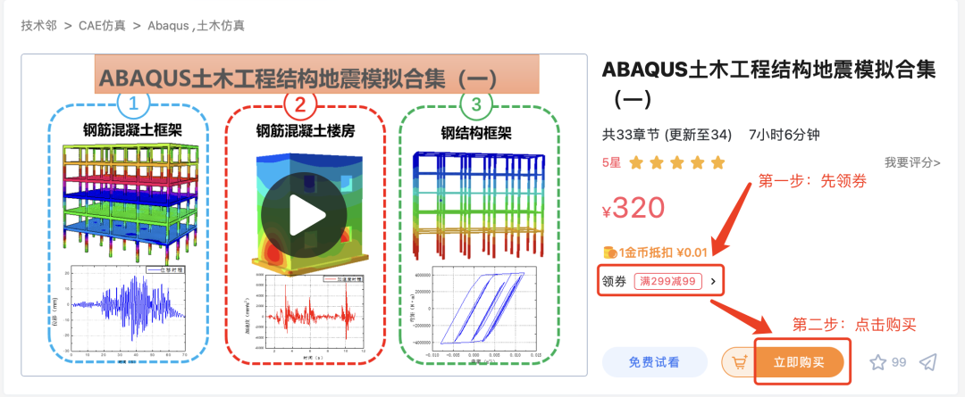

*Note: 2. Courses with amounts less than 299 yuan support order merging payment, and a coupon can be used when the amount reaches 299 yuan.