Code version: 9db1dd5ec5f20d301af076301b8853b7a133eed5
Call Trace
After enabling the Length Tuning Tool, it is linked to DRAWING_TOOL::PlaceTuningPattern through the corresponding binding in DRAWING_TOOL::setTransitions (pcbnew/tools/drawing_tool.cpp). Here is a snippet of the event loop handling code.
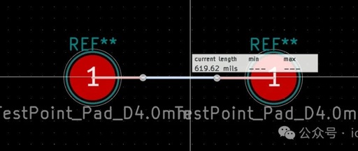
When the cursor is placed over a certain line, the Length Tuning tool displays the length of that line, and the code will enter (still in DRAWING_TOOL::PlaceTuningPattern)
if( evt->IsMotion ) {// omitted code ... updateHoverStatus();} // omitted more codeIn updateHoverStatus(), by calling PCB_TUNING_PATTERN::Update(), it enters ROUTER::StartRouting
router->StartRouting()Entering (for single line length tuning) pcbnew/router/pns_meander_placer.cpp
MEANDER_PLACER::StartHere, the key part of the line length calculation is entered.
Core Code Analysis of Line Length Calculation
The core code entry is here. Because the subsequent retrieval of the displayed calculated length is to compute the value of m_tunedPath, this is the core part of the calculation.
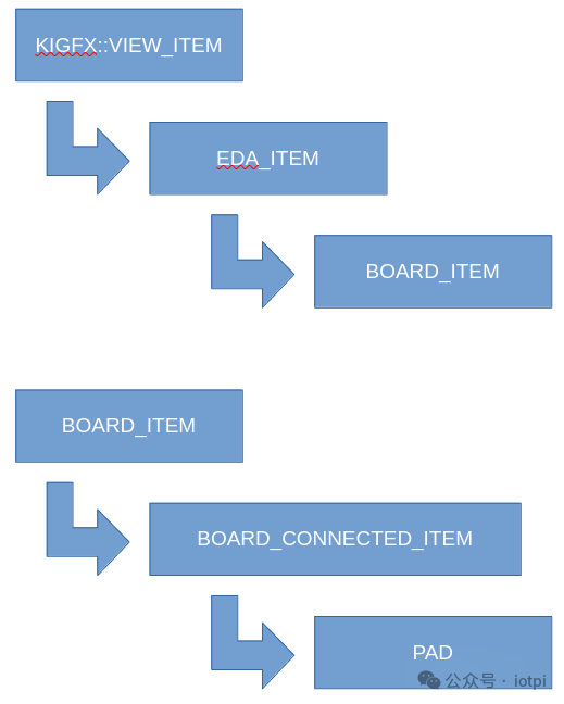
74 TOPOLOGY topo( m_world ); 1 ref 75 m_tunedPath = topo.AssembleTuningPath( m_initialSegment, &m_startPad_n, &m_endPad_n );Inheritance Relationships
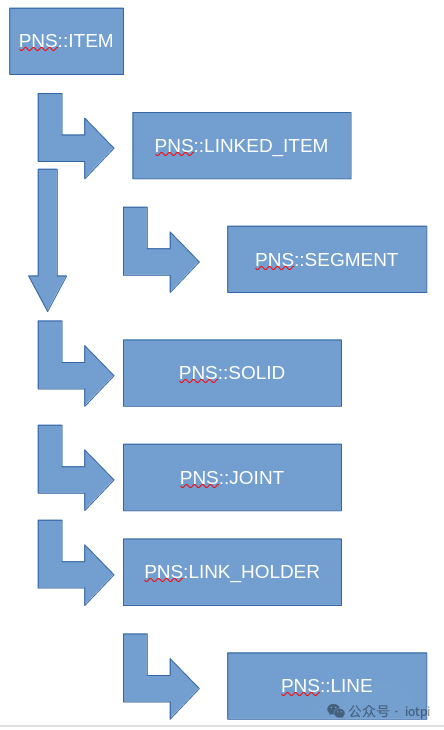
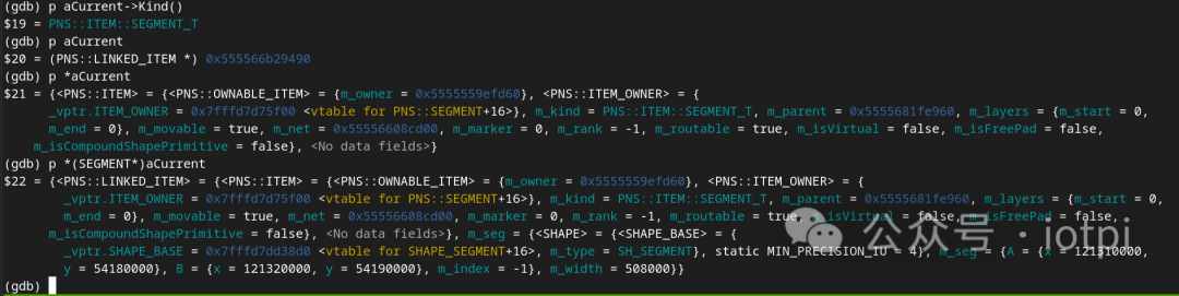
In the program, you can determine the actual type of the current pointer/object by calling
PNS::ITEM::Kind()to determine the actual type of the current pointer/object:
PNS::ITEM
Base class for PNS router board items, implementing common properties for all PCB elements.
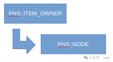
PNS::NODE
pcbnew/router/pns_node.h
NODE is used to store the router’s “world”, which includes all tracks, vias, and solids, in a hierarchical and indexed manner.
PNS::JOINT
A 2D point on a given set of layers and belonging to a certain net, that links together a number of board items. A hash table of joints is used by the router to follow connectivity between the items.
Vias and pads, connection points between two lines, can also be a JOINT. It internally defines multiple methods to determine the actual type of this JOINT.
96 /** 97 * Checks if a joint connects two segments of the same net, layer, and width. 98 * @param aAllowLockedSegs will consider joints between locked and unlocked segments as trivial 99 * @return true if the joint is a trivial line corner 100 */ 101 bool IsLineCorner( bool aAllowLockedSegs = false ) const; 150 bool IsNonFanoutVia() const; 172 bool IsStitchingVia() const; 177 bool IsTraceWidthChange() const;PNS::LINE
Represents a line on the PCB that connects two non-trivial joints, i.e., vias, pads, multiple traces, or junctions of two differently width traces, or combinations thereof. PNS::LINE is not stored within the model (NODE). Instead, they are based on the combination of the vias/pads/segments that contain or start or end this line. (See comments in pcbnew/router/pns_line.h)
PNS::TOPOLOGY
pcbnew/router/pns_topology.h
Calculates the topological properties of a NODE/world.
PNS::TOPOLOGY::AssembleTrivialPath
Assemble a trivial path between two joints given a starting item
Algorithm Analysis
Example PCB
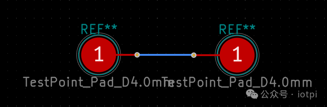
Simplified kicad_pcb file content
(net 0 "")(footprint "TestPoint:TestPoint_Pad_D4.0mm" (at 113.34 54.19) (pad "1" smd circle (at 0 0) (size 4 4) (layers "F.Cu" "F.Mask") (uuid "6baca6a6-e3ec-422e-8255-1ec74843a0d0") ))(footprint "TestPoint:TestPoint_Pad_D4.0mm" (layer "F.Cu") (uuid "a1b08514-55a3-404d-8cf1-e425fa312934") (at 129.07 54.21) (pad "1" smd circle (at 0 0) (size 4 4) (layers "F.Cu" "F.Mask") (uuid "efe3ecd5-3fc1-4341-b837-57f85992cbfe") )) (segment (start 124.14 54.21) (end 129.07 54.21) (width 0.2) (layer "F.Cu") (net 0) (uuid "14e13181-32a3-4a99-92ee-58914e592582") ) (segment (start 113.34 54.19) (end 117.7 54.19) (width 0.2) (layer "F.Cu") (net 0) (uuid "7e88cb31-5757-4ba5-8a5f-ddf7daf03ebf") ) (segment (start 117.7 54.19) (end 117.71 54.2) (width 0.2) (layer "F.Cu") (net 0) (uuid "98dd8262-83c0-425a-9f5d-b12bb95a1462") ) (via (at 117.71 54.2) (size 0.6) (drill 0.3) (layers "F.Cu" "B.Cu") (net 0) (uuid "40af5aa0-cd97-40bd-94fe-1d4d088d00be") ) (via (at 124.14 54.21) (size 0.6) (drill 0.3) (layers "F.Cu" "B.Cu") (net 0) (uuid "674e89f5-457e-46a1-86c6-b68c22d485b1") ) (segment (start 117.71 54.2) (end 124.13 54.2) (width 0.2) (layer "B.Cu") (net 0) (uuid "4140aa44-32a2-49f1-a53c-69d33340e76c") ) (segment (start 124.13 54.2) (end 124.14 54.21) (width 0.2) (layer "B.Cu") (net 0) (uuid "7df491dc-65ca-42dc-bb4c-245e1d145486") )Analysis of kicad_pcb format, see KiCad code reading notes: PCB file format
Run pcbnew with gdb, set a breakpoint at TOPOLOGY::AssembleTuningPath
Use the Length Tuning tool to calculate the line length
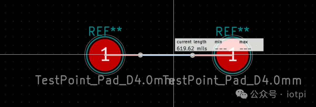
Enter the breakpoint
(gdb) list 332327328 return path;329 }330331332 const ITEM_SET TOPOLOGY::AssembleTuningPath( ITEM* aStart, SOLID** aStartPad, SOLID** aEndPad )333 {334 std::pair<const JOINT*, const JOINT*> joints;335 ITEM_SET initialPath = AssembleTrivialPath( aStart, &joints, true );336(gdb) p *aStart$2 = {<PNS::OWNABLE_ITEM> = {m_owner = 0x5555579ff000}, <PNS::ITEM_OWNER> = {_vptr.ITEM_OWNER = 0x7fffead8ef80 <vtable for PNS::SEGMENT+16>}, m_kind = PNS::ITEM::SEGMENT_T, m_parent = 0x555556932280, m_layers = {m_start = 31, m_end = 31}, m_movable = true, m_net = 0x55555694e980, m_marker = 0, m_rank = -1, m_routable = true, m_isVirtual = false, m_isFreePad = false, m_isCompoundShapePrimitive = false}(gdb) p *(SEGMENT *)aStart$3 = {<PNS::LINKED_ITEM> = {<PNS::ITEM> = {<PNS::OWNABLE_ITEM> = {m_owner = 0x5555579ff000}, <PNS::ITEM_OWNER> = { _vptr.ITEM_OWNER = 0x7fffead8ef80 <vtable for PNS::SEGMENT+16>}, m_kind = PNS::ITEM::SEGMENT_T, m_parent = 0x555556932280, m_layers = {m_start = 31, m_end = 31}, m_movable = true, m_net = 0x55555694e980, m_marker = 0, m_rank = -1, m_routable = true, m_isVirtual = false, m_isFreePad = false, m_isCompoundShapePrimitive = false}, <No data fields>}, m_seg = {<SHAPE> = {<SHAPE_BASE> = { _vptr.SHAPE_BASE = 0x7fffeadec950 <vtable for SHAPE_SEGMENT+16>, m_type = SH_SEGMENT}, static MIN_PRECISION_IU = 4}, m_seg = {A = {x = 117710000, y = 54200000}, B = {x = 124130000, y = 54200000}, m_index = -1}, m_width = 200000}}Seeing the values of m_seg, we correspond to the kicad_pcb file
(segment (start 117.71 54.2) (end 124.13 54.2) (width 0.2) (layer "B.Cu") (net 0) (uuid "4140aa44-32a2-49f1-a53c-69d33340e76c") )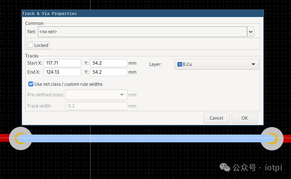
Step through, entering TOPOLOGY::AssembleTrivialPath
(gdb) list275276 const ITEM_SET TOPOLOGY::AssembleTrivialPath( ITEM* aStart,277 std::pair<const JOINT*, const JOINT*>* aTerminalJoints,278 bool aFollowLockedSegments )279 {280 ITEM_SET path;281 LINKED_ITEM* seg = nullptr;282283 if( aStart->Kind() == ITEM::VIA_T )284 {(gdb) n281 LINKED_ITEM* seg = nullptr;(gdb)283 if( aStart->Kind() == ITEM::VIA_T )(gdb)302 else if( aStart->OfKind( ITEM::SEGMENT_T | ITEM::ARC_T ) )(gdb)304 seg = static_cast<LINKED_ITEM*>( aStart );(gdb)307 if( !seg )Currently, we are in the simplest case where the length tuning tool selects a segment
Next, we enter NODE::AssembleLine
PNS::NODE::AssembleLine
Follow the joint map to assemble a line connecting two non-trivial joints starting from segment aSeg.
Here, MaxVerts is defined, limiting the minimum number of nodes for the subsequent algorithm.
int i_start = MaxVerts / 2;This indicates that the algorithm for this line (PNS::LINE) starts construction from the midpoint of the defined array (the algorithm, or data structure, defines directions to the left and right, so the implementation uses an array and defines the starting point from the middle).
PNS::NODE::followLine
Scan the joint map, forming a line starting from segment (current)
(gdb) list958959 void NODE::followLine( LINKED_ITEM* aCurrent, bool aScanDirection, int& aPos, int aLimit,960 VECTOR2I* aCorners, LINKED_ITEM** aSegments, bool* aArcReversed,961 bool& aGuardHit, bool aStopAtLockedJoints, bool aFollowLockedSegments )962 {963 bool prevReversed = false;964965 const VECTOR2I guard = aCurrent->Anchor( aScanDirection );966967 for( int count = 0 ; ; ++count )Here, starting from the current segment’s point, using the midpoint of the array, it searches in one direction.
Previously, we saw that PNS::SEGMENT contains two points, A and B. Here, aCurrent is a SEGMENT, and aCurrent->Anchor() calls the implementation in pns_segment.h, which returns A when aScanDirection == false, and B otherwise.
107 virtual VECTOR2I Anchor( int n ) const override 52 b.refs|1 ref 108 { 109 if( n == 0 ) 110 return m_seg.GetSeg().A; 111 else 112 return m_seg.GetSeg().B; 113 }The following is the formal search construction part of the code
(gdb) l 974967 for( int count = 0 ; ; ++count )968 {969 const VECTOR2I p = aCurrent->Anchor( aScanDirection ^ prevReversed );970 const JOINT* jt = FindJoint( p, aCurrent );971972 wxCHECK( jt, /* void */ );973974 aCorners[aPos] = jt->Pos();975 aSegments[aPos] = aCurrent;976 aArcReversed[aPos] = false;977978 if( aCurrent->Kind() == ITEM::ARC_T )979 {980 if( ( aScanDirection && jt->Pos() == aCurrent->Anchor( 0 ) )981 || ( !aScanDirection && jt->Pos() == aCurrent->Anchor( 1 ) ) )Here, note that i starts from i_start + 1, thus skipping the first starting position. Therefore, if there is a third line segment here, causing the line length calculation to be interrupted, the length calculation on the right will not include this via.
Returning to pcbnew/router/pns_topology.cpp
312 LINE l = m_world->AssembleLine( seg, nullptr, false, aFollowLockedSegments ); 314 path.Add( l );The path (the returned m_tunedPath) adds the first line segment l.
Subsequently, starting from this line, it continues to build the path to the left and right (only logically left and right, not graphically),
319 followTrivialPath( &l, false, path, &jointB, aFollowLockedSegments ); 320 followTrivialPath( &l, true, path, &jointA, aFollowLockedSegments );PNS::TOPOLOGY::followTrivialPath
has logic similar to the previous followLine, but executes NODE::AssembleLine multiple times in the loop, due to the conditional checks
216 if( !visited.insert( last ).second 217 || ( !jt->IsNonFanoutVia() && !jt->IsTraceWidthChange() ) ) 218 { 219 if( aTerminalJoint ) 220 *aTerminalJoint = jt; 221 222 return false; 223 }Here, IsNonFanoutVia causes the path construction process to stop when it’s not a via connecting two lines.
The construction of the track length part of the code roughly follows this flow, and there are some detail checks that interested friends need to cross-reference with the source code process to understand.
Below is the calculation of line length
PNS::MEANDER_PLACER::origPathLength
94 long long int MEANDER_PLACER::origPathLength() const 2 refs|2 derived 95 { 96 return m_padToDieLength + lineLength( m_tunedPath, m_startPad_n, m_endPad_n ); 97 }PNS::MEANDER_PLACER_BASE::lineLength
335 /** 336 * If there is a start pad but the pad's layers do not overlap the first track layer, then there must be a 337 * fanout via on the line. If there isn't, we still need to have the via back to the pad, so count the distance 338 * in the line tuning 339 */ 340 start_via = aStartPad &&& ( !aStartPad->LayersOverlap( start_item ) ); 341 end_via = aEndPad &&& ( !aEndPad->LayersOverlap( end_item ) );Here, only when startPad overlaps with start_item (the first ITEM), is start_via set; only when endPad overlaps with end_item (the last ITEM), is end_via set, and during the final line length calculation, the board thickness is added to the total length.
However, I still do not fully understand how this situation arises.
The subsequent part is to traverse all segments and calculate the total.
343 for( int idx = 0; idx < aLine.Size(); idx++ ) 7 refs 344 { 345 const ITEM* item = aLine[idx]; 2 refs 346 347 if( const LINE* l = dyn_cast<const LINE*>( item ) ) 2 refs 348 { 349 total += l->CLine().Length(); 350 } 351 else if( item->OfKind( ITEM::VIA_T ) &&& idx > 0 &&& idx < aLine.Size() - 1 ) 352 { 353 int layerPrev = aLine[idx - 1]->Layer(); 2 refs 354 int layerNext = aLine[idx + 1]->Layer(); 2 refs 355 356 if( layerPrev != layerNext ) 357 total += m_router->GetInterface()->StackupHeight( layerPrev, layerNext ); 358 } 359 }Note here that when a via is encountered, an additional distance for the via will be added.
The general line length calculation process is as described above. To add pad-to-pad line length calculation, there are still many parts that need to be modified, and to reproduce most of the calculation process, compatibility with existing calculation modes also needs to be considered.
Note: If you want to receive KiCad content updates immediately, please click on the card below, follow, and set it as a star.
Common collection summary:
-
KiCad usage experience sharing -
KiCad design projects(Made with KiCad) -
Common problems and solutions -
KiCad development notes