1. Introduction
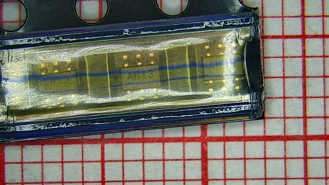
The MCP4017 chip I purchased has just been delivered by the courier. This is an electronic potentiometer, or rather an electronic variable resistor, intended for future development. Below is a preliminary test of its characteristics.
2. Test Circuit
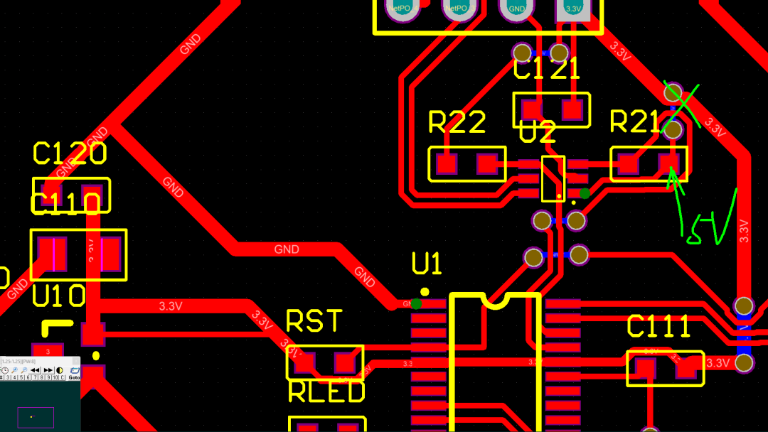
The designed schematic is based on the STM32F030 microcontroller, connected to the MCP4017 via the I2C interface. The W and B terminals of the MCP4017 are connected to external interfaces. The XC6206 provides a stable 3.3V power supply. Below is the design of the circuit board. A single-sided PCB design is used, suitable for a one-minute board-making method. It includes six flying leads.
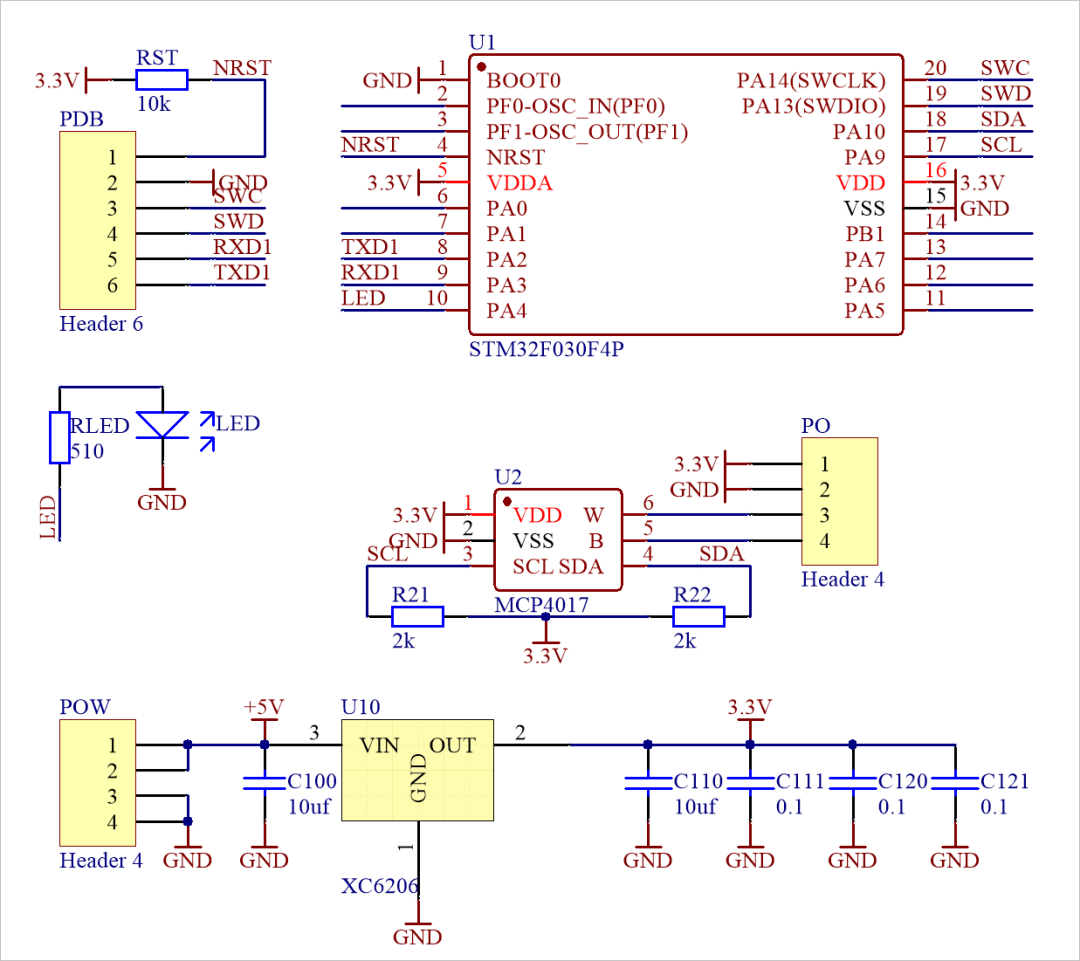
▲ Figure 1.2.1 Test Circuit Schematic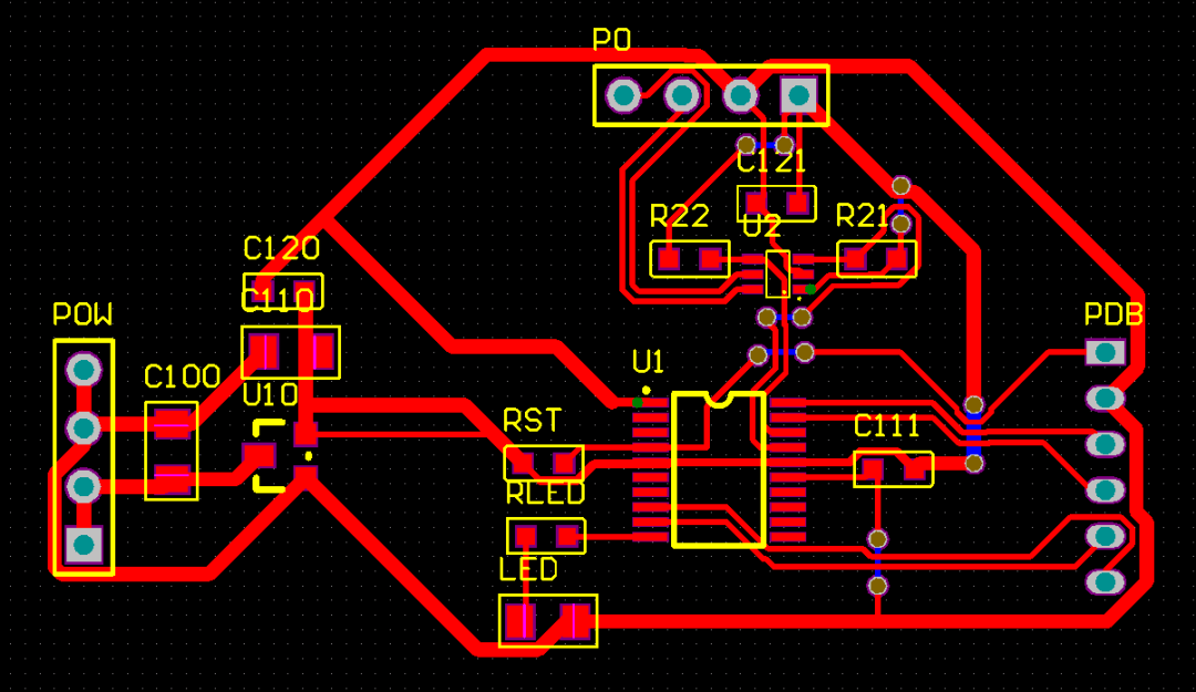
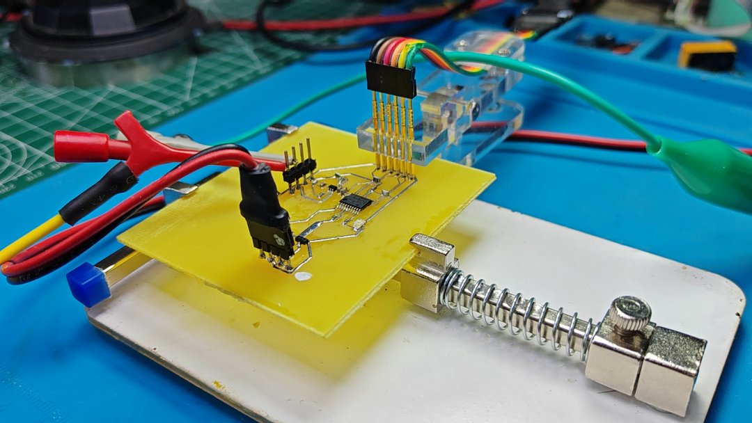
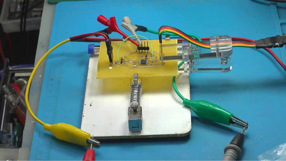
▲ Figure 1.2.2 Test Circuit PCBOne minute later, the test circuit board was obtained. The PCB was made perfectly. The leads here are all 10mil, and I think next time I will test a PCB made with 6mil wire diameter. It should not be too much of a challenge.

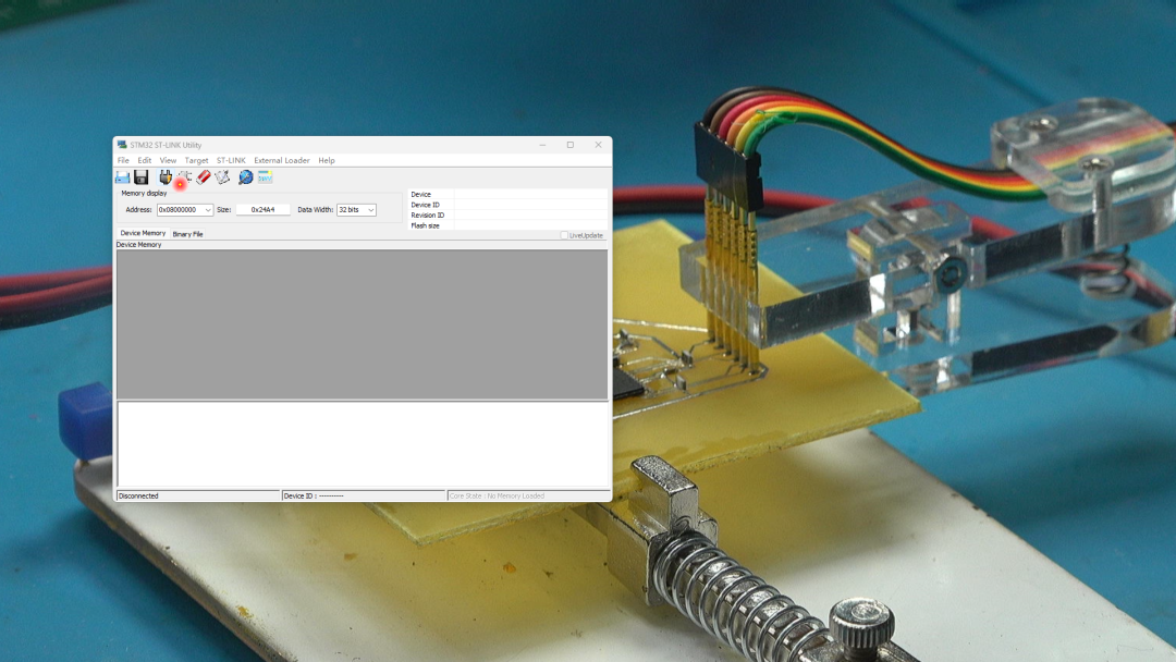
Soldering the PCB, it is placed on the debugging platform. A 5V power supply is introduced, and the 3.3V power supply on the PCB is measured to be normal. Using a probe clip, the ST-LINK is connected to the SWD debug port of the microcontroller. Now the ST-LINK can properly access the microcontroller.
3. Software Debugging
The program framework is generated by CubeMX. First, the LED blinking program is written and downloaded to the circuit for testing.
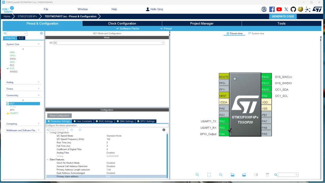
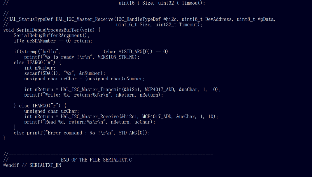
The MCP4017 is controlled through the I2C program. By sending a byte, the resistance of the MCP4017 is set. The address of the MCP4017 is the value corresponding to its 7-bit address left-shifted by one. Using the Receive function, the current content of the MCP4017’s internal RAM can be read back. Manual testing shows that these read and write operations are normal.
Next, the settings of the MCP4017 are measured from 0 to 127, corresponding to the resistance between the W and B pins. The change in resistance is observed. It was surprising to find that the output resistance remained linear until around 30, but then fluctuated as the settings increased. Testing again yields the same results. Oh my god. How could this be the case?
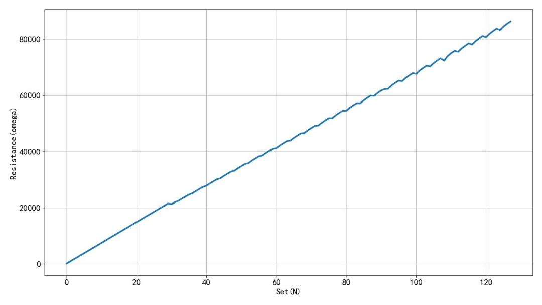
▲ Figure 1.3.1 Measurement ResultsAccording to the measurement results, when set to 0, the resistance is still 134 ohms, which should be the conduction resistance of the internal analog switch. It is related to the operating voltage of the device.
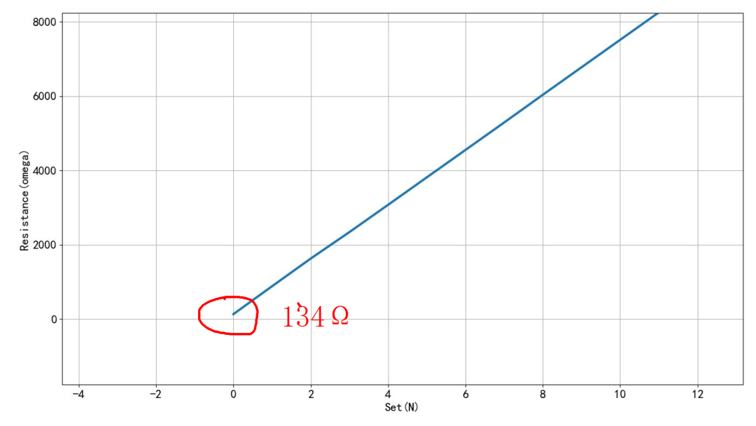
By modifying the power supply of the MCP4017, the wire originally connected to 3.3V is disconnected. It is connected to 5V, and the resistance between W and B is re-measured when set to 0. It can be seen that it has decreased to 103.5 ohms.
※ Conclusion ※
This article tested the characteristics of the electronic potentiometer MCP4017. Through the I2C bus, its resistance between the sliding terminal and the fixed terminal was controlled, with a total of 128 levels of resistance and a total resistance of 86k ohms. It is unclear why this resistance does not show a good linear relationship with the set values. If anyone knows the reason, please feel free to advise.
MCP4017 7-bit single Digital POT in SC70 w/I2C: https://www.microchip.com/en-us/product/MCP4017